| A spin Esaki diode |
|
Our group has demonstrated electrical electron spin injection via interband tunneling in ferromagnetic/nonmagnetic semiconductor Esaki diodes. An interband tunnel junction between ferromagnetic p+-(Ga,Mn)As and nonmagnetic n+-GaAs under reverse-bias allows spin-polarized tunneling of electrons from the valence band of (Ga,Mn)As to the conduction band of n+-GaAs. The spin polarization of tunneled electrons is probed by circular polarization of electroluminescence (EL) from an n-GaAs/InGaAs/p-GaAs light emitting structure integrated with the diode. Clear hysteresis loop with ±6.5% remanence is observed in the magnetic-field dependence of the EL polarization at 6 K, below the Curie temperature of (Ga,Mn)As. |
 |
| Figure1. | The schematic band structure of a spin Esaki diode. When forward-bias is applied to the non-magnetic pn junction below Tc, spin polarized holes generated in the (Ga,Mn)As layer can tunnel through the p+-(Ga,Mn)As/n+-GaAs junction. Consequently, spin polarized electrons are carried into non-magnetic active region and recombined with unpolarized holes coming from p-GaAs layer at quantum well (QW). The electron spin polarization is examined by circular polarized light of electroluminescense (EL) from the (In,Ga)As QW as an edge emission. |
 |
| Figure2. | An experimental setup for the polarization measurement. To measure circular polarization of electroluminescense in an applied magnetic field,samples are processed for an edge emission and placed in magneto
optical Cryostat with Faraday configuration. The emission is analyzed with
Babinet-Soleil phase compensator and a linear polarizing beam splitter to
separate right and left polarized components. Each component is detected with
a silicon photo diode. |
 |
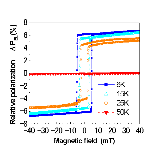
| Figure3 | The changes of the EL polarization as a function of in-plane magnetic field for temperatures between 6 and 50K. The polarization is clearly hysteretic and the coercive field decreases from 5 to 0 mT as the temperature is raised from 6K to near Tc (= 60K). The maximum polarization is ±6.5% at 6K. |
 |
| Figure4 | The changes of the EL polarization of electron and hole spin injection devices. We have grown electron and hole spin injection devices to compare the polarization between these two devices. These devices have almost the same layer thicknesses from (Ga,Mn)As to InGaAs and same indium composition of InGaAs QW. DPEL of hole spin injection is ±0.8%. However, DPEL of electron spin injection is ±3.8%, which is about 5 times larger than that of the hole spin injection and it strongly indicates the origin of DPEL being electrical spin injection. |
| Publication |
|---|
| M. Kohda, Y. Ohno, K. Takamura, F. Matsukura, and H. Ohno, Japansese Journal of Applied Physics, Vol. 40, L1274-L1276 (2001). |